We have strived to proffer a new and vibrant perspective

Our Products


We Are Lontron

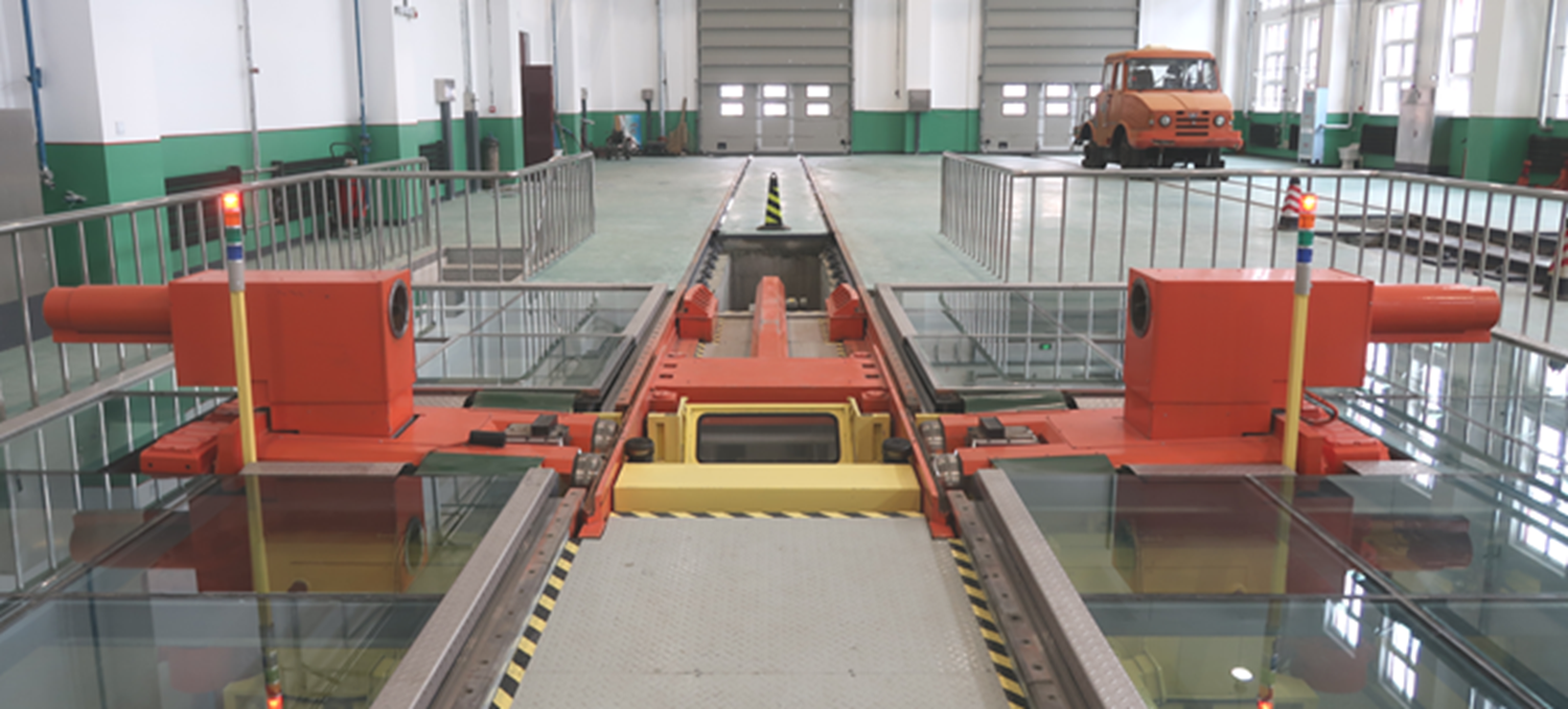
Underfloor Wheel Lathe

CNC Under-floor Wheel Lathe is applicable to all types of CRH EMUs and existing passenger cars and freight cars, realizing the automatic re-profiling of wheel flange tread without disassembly of the wheel set, as well as the automatic re-profiling of the flange tread of a single wheel set. It can meet the requirement for simultaneously automatic re-profiling of two wheel sets of one bogie.

Functional Description

● The CNC under-floor wheel loathe is provided with a semi-closed loop control function, which can realize the automatic turning of the wheelset tread profile.  
●  The lathe is provided with the optional function between simultaneous machining at both sides and machining at a single side and is provided with automatic and manual control modes. 
●  The working overhang of the press-down mechanism is less than 300 mm and replaceable spindle box clamps are provided, which are applicable to the automatic re-profiling of wheelset tread for all types of CRH EMUs and other vehicles. The elevation of the press-down mechanism 
(excluding the clamps) is consistent with that of the rail between vehicles, so as to achieve the machining of wheelset under the special conditions of the lower vehicle apron and closer to the spindle box. 
●  Friction roller driving mode is adopted for the main drive. The friction-driving rollers are used to support and drive the wheel set to be machined and realize the radial positioning of the wheelset. Independent left and right roller racks are employed for friction driving, with each roller rack driven 
by a separate spindle motor. 
●  The lathe is provided with an automatic measuring device that can measure the axial position of the wheelset to be machined and realize automatic tool setting. With the help of a measuring device and computer system, the tool-cutting system of the lathe can carry out automatic alignment cutting for the wheelset with an axial positioning function. 
 ●  By applying the special interface for wheelset machining on the same operation interface, it is able to select the information input of train, vehicle, wheelset, wheel type, and operator and display such information. 
●  Measured values for wheelset before machining: wheel diameter, Qr value, the distance between backs of wheel flanges, tread run-out and axial play, wheel flange thickness, wheel flange height, and contour drawing of wheel flange tread. 
●  Target values of machining: wheel diameter and wheel flange thickness. 
●  Measured values for wheelset after machining: wheel diameter, Qr value, the distance between backs of wheel flanges, tread run-out and axial play, wheel flange thickness, wheel flange height, and contour drawing of wheel flange tread. 
●  The control system is provided with the function of "machining suggestion", which can realize economical re-profiling and display the machining procedures with different wheel flange thicknesses and wheel diameters on the operator interface for the operator's choice, so as to make the wheel diameter difference meet the limit requirement specified for operation.
●  The contour of wheelset is measured by the continuous measurement method to guarantee the measurement accuracy of the contour, make the quantity of measuring points be adjustable between 50 and 100, and really achieve rational and economical re-profiling. 
●  The lathe is provided with the fault self-diagnosis function, which can make judgments accurately, give an alarm without delay and display the fault information in case of lathe fault.  
●  The lathe is provided with safety protection and a control function. 
●  The lathe can send its current status to the safety monitoring system so that the requirement for safety monitoring is met.  
●  The replaceable special machining tool for the wheelset is used, showing a good chip-breaking effect. In addition, a chip breaker and an enclosed collection device for chip removal are provided, so that the iron chip can be automatically transmitted through the enclosed passage to the iron chip 
box above ground within the workshop. 
●  The lathe is equipped with standard wheels, which have the functions of adjustment and calibration. 
●  The lathe is provided with an anti-slip function, which can realize automatic tool retracting or shutdown in case of a cutting slip (stuck). 
●  The lathe is provided with the anti-misoperation function and the alarm display function in case that the selected action can not be carried out in the current state. 
●  The lathe is provided with the return function from cutting interruption and the operation panel is provided with the function key for tool replacement, so as to meet the tool replacement requirement during cutting. 
●  The lathe is provided with the zone machining function, which can select the machining zone based on the actual conditions of the contour, so as to reduce the unnecessary non-cutting stroke.  
●  The lathe is provided with the measurement function during machining, which can follow up and measure the actual diameter of wheel set simultaneously with re-profiling in case of multiple tool machining. 
●  The lathe is provided with a lubricating function, and a recovery device must be equipped when the lubricating oil is applied to meet the requirement for environmental protection. 
●  The traction device can ensure that the positioning accuracy of the wheelset is ± 50 mm and the maximum speed passing the under-floor lathe is 5 km/h. 
●  The human-computer interface is good and an advanced digital programming system and a solidification program are provided.  
●  The lathe is provided with data printing, recording, storage, and output functions. 
●  The electrical cabinet, electrical element, motor, reduction gearbox, bearing, straight guide rail, lead screw, and hydraulic system element shall be selected from the products of internationally famous brands. 
●  The electrical cabinet shall be provided with a dedicated industrial air conditioner, which has a protection class of IP54 and the function of electromagnetic compatibility (EMC). 
●  The oil inlet and outlet shall be provided with the anti-blocking alarm function. 
●  Safety lights shall be provided at locations easy to be observed and these lights shall display the initial positioning state of the wheelset, especially for directing the feeding and retracting of the vehicle to be machined. 
●  The lathe is provided with a networking function that can exchange information with the tread diagnosis system of the wheelset, as well as the interface with the EMU information management system.

Technical Specifications

●  Rated power:  ≤ 100 kW  
●  Temperature control of electrical cabinet: Controlled by industrial air conditioner 
●  Machining efficiency: ≤35 min/bogie 
●  Equipment noise (excluding that in the cutting state)  ≤75dB  
●  Operation interface of CNC system: Chinese or Optional
●  Range of wheel set machining:
●  Track gauge: 1435mm or Customized 
●  Range of wheel diameter: φ650mm~φ1400mm 
●  Range of tread width: 90mm~160mm 
●  Range of axle length: 1600mm~2600mm 
●  Distance between backs of wheel flanges: 1353mm±2mm 
●   Axle load: ≤250kN 
●  Driving and positioning devices:
●  Driving mode of main transmission: Friction power drive by roller 
●  Spindle speed steps: AC variable frequency stepless adjustable 
●  Diameter of friction roller: ≥220mm 
●  Distance between centers of friction rollers: ≥440mm
●  Power of main driving unit: 30 kW×2=60kW 
●  Protection class of main drive: IP54 
●  Tool rest (single tool test) :
●  Range of feeds (feeding speed): 0~2.5 mm/r 
●  Moving speed of tool rest: Z-axis 4.7m/min  X-axis 2m/min 
●  Maximum cutting sectional area: ≤10 mm² 
●  Cutting force: ≤26 kN 
●  Range of cutting speed: 30 ~ 120 m/min 
●  Measuring device (single measuring device) :
●  System of units for measuring system: Metric system 
●  Measuring transducer element: HEIDENHAIN, AMO 
●  Quantity of measuring axis: Six (including UX-axis, VZ-axis and AD-axis at each side) 
●  Diameter measuring method: circumferential contact measurement 
●  Quantity of roller for diameter measurement: 2 sets 
●  Diameter of roller for diameter measurement: 80mm 
●  Range of diameter measurement: Ф650- 1400 mm 
●  Number of digits after the decimal point kept for diameter measurement: 2 (i.e. the indicated measured value shall be accurate to 0.01 mm) 
●  Contour and abrasion measuring method: continuously scanning measurement. 
●  Quantity of roller for contour and abrasion measurement: 2 sets 
●  Diameter of roller for contour and abrasion measurement: 80mm 
●  Quantity of contour measuring point: 50-100 points 
●  Number of digits after the decimal point kept for abrasion measurement: 2 
●  Mode of contact between measuring head and inner side: pre-compressing mode. 
●  Inner side measuring method: pre-compressing circumferential contact measurement. 
●  Positioning and measuring head for distance between backs of wheel flanges: 2 sets 
●  Pre-compressing stroke of measuring head: 5mm
●  Quantity and distribution of measuring point: circumferentially continuous point on the inner side. 
●  Machining accuracy:
●  Maximum difference of wheel diameter of the same axle: ≤ 0.10 mm 
●  Maximum difference of wheel diameter of the same bogie: ≤ 0.30 mm 
●  Radial run-out of the measured circle height: ≤ 0.10 mm 
●  Run-out of end face: ≤ 0.30 mm 
●  Geometric deviation of contour: ≤ 0.20 mm 
●  Surface roughness for contour machining: Ra≤12.5 µm 
●  Others:
●  Installation dimension of lathe (L × W × H): 8000mm×6800mm×2300mm 
●  Weight of lathe: 40000kg

Stay Updated With Our Newsletter